Source: https://done.land/tools/breadboard/powersupply/hw-131/
Source: https://done.land/tools/breadboard/powersupply/hw-131/
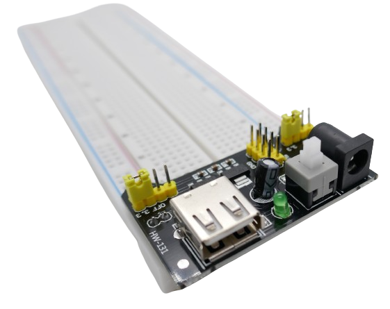
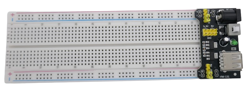
HW-131 is a buck converter on a special breakout board designed for MB102 breadboards (the most common type).
It plugs directly into the breadboard power rails which coincidentally tightly secures the power supply to the breadboard.
Power Inputs
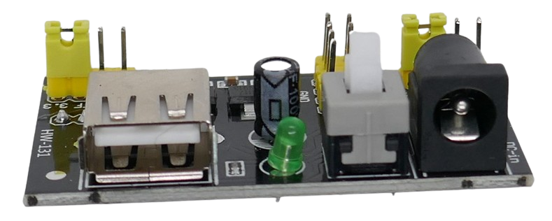
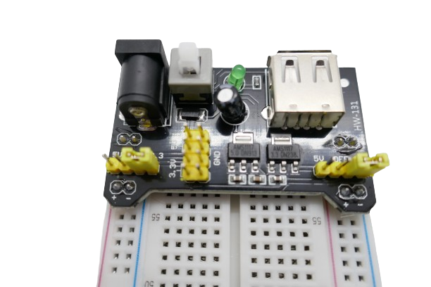
The board accepts input power via a cinch power socket (6.5-12V).
Output Power
A large latched push button can be used to turn output power on and off. When the power is turned on, a green LED lights up.
The board converts the input voltage to 3.3V and 5V simultaneously.
Both voltages are available via 2x2 pins next to the power button.
5V is also available via a USB-A connector.
The buck converter on the board is rated for a maximum output current of 700mA. This power supply is well suited for most prototyping. If your circuit requires unusually high currents, definitely use a different power supply.
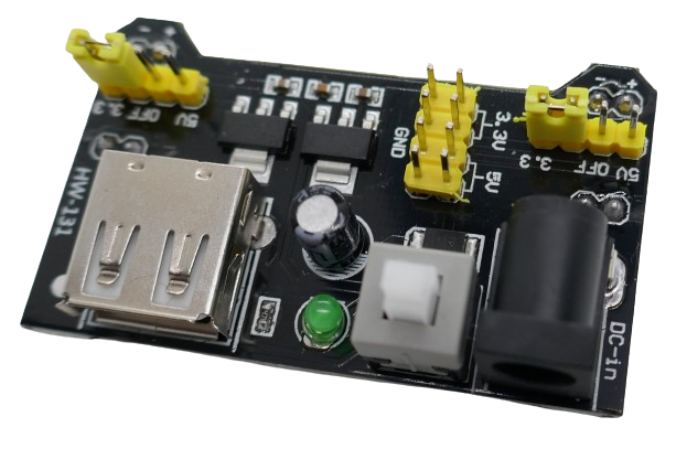
Setting Rail Output Voltage
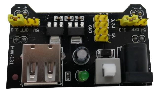
The voltage that is supplied to the breadboard rail can be flexibly set using jumpers on each side / on each rail sepately.
You can set the voltage to identical values on both breadboard rails, or you can set 5V to one rail and 3.3V to the other rail. If you remove the jumper, the rail is not receiving any power.
Connecting Breadboard Rails
The output power that you set through the two sets of jumpers is available at pins on the board backside.
These pins directly plug into the breadboard power rails:
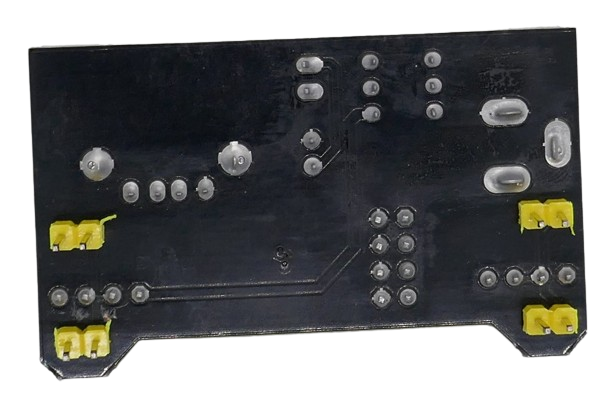
Make sure you place the power module on the correct side of the breadboard so that + and - align correctly to the power rails:
The pins marked + should plug into the rail marked with the red line, and the pins marked - need to go into the pins marked with the blue line.
 ]
]